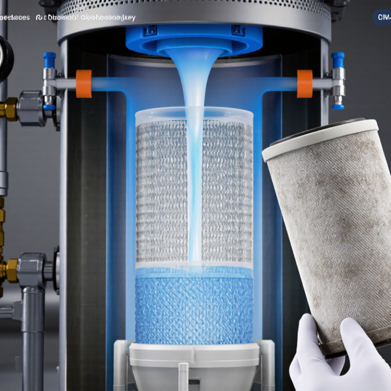
A Polymer Candle Filter Element is a cylindrical component used to separate solid particles from process fluids or gases. Its shape allows it to sit inside a filter vessel, where fluid passes through a porous polymer medium and particles collect on the surface or within its structure. The exact design depends on the polymer, pore size, operating temperature, pressure, and chemical exposure. Small details matter.
In practical use, operators may inspect a removed element for uneven deposits, surface damage, or changes in flow. These clues can help identify a developing filtration problem, though they do not replace testing or the equipment supplier’s guidance. Polymer elements can offer useful corrosion resistance and tailored filtration performance, but no single material suits every process. That distinction is easy to miss.
This guide explains how a Polymer Candle Filter Element works, which design factors affect its performance, and what users should consider during selection and maintenance. It also distinguishes general advantages from application-specific claims. Real operating conditions are rarely as tidy as a product sheet suggests. A careful comparison of process requirements, material compatibility, and cleaning practices can therefore support a more reliable choice.
What Is a Polymer Candle Filter Element? Definition and Filtration Role
A polymer candle filter element is a long, cylindrical filter used in polymer melt processing. It contains a porous metal structure, often with a central flow channel and layered filtration media. Molten polymer passes through the element, while gels, unmelted particles, carbonized material, and metal fragments remain trapped. The term “candle” describes its shape, not a combustion function. Simple enough.
Its filtration role is practical and measurable. Cleaner melt can reduce black specks, blocked spinnerets, surface defects, and unexpected production stops. Engineers normally evaluate micron retention, pressure drop, temperature resistance, flow rate, and dirt-holding capacity. A rising differential pressure usually signals contamination buildup, although it can also indicate unstable melt conditions. This distinction is sometimes overlooked.
The scale of the industry explains the need for reliable filtration. Plastics Europe reported global plastics production of about 400.3 million tonnes in 2022. Meanwhile, the OECD’s Global Plastics Outlook reported that only 9% of plastic waste was recycled in 2019. Recycled feedstock often carries greater variability, making melt filtration more demanding. A candle element can improve consistency, but it cannot correct poor drying, thermal degradation, or badly controlled mixing. That limitation matters. Filter selection should follow actual polymer chemistry, operating temperature, contamination type, and line pressure. In practice, there is no universally “best” element; the wrong pore structure may increase energy use or shorten service life.
A polymer candle filter element is a cylindrical, porous filter component used to remove gels, undissolved particles, catalyst residues, and other contaminants from polymer melts or process liquids. Its long, tubular design provides a large filtration area within a compact housing.
Filtration role: Polymer candle filters are selected according to the required contaminant retention level. Coarse stages commonly remove larger particles, while polishing stages use finer ratings to protect product quality and downstream equipment. Actual performance depends on polymer viscosity, temperature, pressure, filter media, and whether the rating is nominal or absolute.
A polymer candle filter element is a tubular device made from porous synthetic media. Its internal structure allows liquid to pass while retaining suspended particles. The element can operate inside a pressure vessel or housing. Its cylindrical shape provides useful filtration area in a compact space.
Nominal ratings commonly range from 0.5 to 100 μm. A 0.5 μm nominal element targets much finer particles than a 25 μm element. However, nominal does not mean absolute removal. The rating usually indicates approximate particle retention under defined test conditions. Real performance changes with particle shape, concentration, viscosity, and flow rate. That distinction matters.
During filter evaluations, engineers should compare the rating with actual process demands. A clear liquid may require a finer element, while a heavily loaded stream may need a coarser prefilter. Excessive pressure can deform some polymer media or accelerate blinding. Temperature and chemical compatibility also deserve careful checks. Polypropylene, polyethylene, and fluoropolymer structures do not behave identically. Not absolute.
In practice, operators should record initial pressure drop and monitor its increase during service. A sudden rise may indicate surface loading, poor upstream control, or an unsuitable rating.
Micron numbers can look precise, yet test methods differ between suppliers. This is an area where careful verification is often missing. Pilot testing with the real fluid remains more reliable than choosing from a specification sheet alone.
A polymer candle filter element is a long, hollow cylinder made from porous polymer media. Its shape provides a large filtration area inside a compact housing. In an inside-out design, contaminated liquid enters the central bore. It then moves outward through the polymer wall. Particles remain on the inner surface or within the media structure.
This flow direction makes geometry important. A longer candle increases available area, but it may also raise pressure loss. A wider bore can improve flow distribution. However, poor sealing may allow bypass, making the filter appear effective while releasing particles downstream. The U.S. EPA Membrane Filtration Guidance Manual identifies microfiltration pore ranges of roughly 0.1 to 10 micrometers. Actual capture depends on pore distribution, particle shape, viscosity, and operating pressure. ISO 16889 also shows why beta ratios are more useful than nominal micron ratings. Pore size alone is not a guarantee.
Tips: Check the clean pressure drop first. Then compare it with the loaded value. Watch the inner surface during inspection. Uneven deposits often indicate poor flow distribution. A practical mistake is selecting the smallest stated pore size. That choice may shorten service life sharply. The design is not perfect. Real process data should challenge the specification. Record particle size results, temperature, and flow rate during testing. These details make supplier claims easier to verify.
A polymer candle filter element is a porous, cylindrical component that retains particles as liquid passes through its wall. Its material sets the practical limits. Polypropylene suits many aqueous and chemical services, while other polymers may tolerate different solvents or temperatures. Compatibility must be checked against the actual fluid, concentration, and cleaning method—not a broad material label. Small details matter.
Flow rate is not a fixed property of the candle. It changes with viscosity, filtration area, pore structure, and accumulated solids. ISO 16889:2022 describes a multipass method for evaluating hydraulic filter performance, including particle counts and pressure behavior; it is a useful reference, but not a guarantee of process throughput. Specify flow at a stated fluid temperature and viscosity. Otherwise, two quoted rates may not be comparable.
Differential pressure shows the pressure loss across the element and often rises as particles load the medium. Set a clean-element baseline, then define an alert or changeout limit using system requirements and supplier test data. ISO 2941 provides a method for assessing filter-element collapse or burst resistance. Temperature limits also depend on polymer, exposure time, pressure, and cleaning cycles. A short temperature spike can matter. In practice, teams sometimes overlook that detail; reviewing the full operating cycle is safer than selecting from a single maximum-temperature figure.
| What Is a Polymer Candle Filter Element? - Key Specifications: Material, Flow Rate, Differential Pressure, and Temperature | ||
|---|---|---|
| Specification | Typical Information or Range | What to Consider |
| Purpose | Removes contaminants and gels from polymer melt or process fluid. | Used in polymer processing systems where filtration performance must be matched to the material and process conditions. |
| Filter media | Sintered stainless-steel fiber, woven stainless-steel mesh, or other process-compatible metal media. | Media selection depends on chemical compatibility, operating temperature, required filtration rating, and cleaning method. |
| Support and end fittings | Commonly stainless steel; grades such as 304 or 316L may be used depending on the process. | Confirm compatibility with the polymer, additives, cleaning chemicals, and equipment connections. |
| Nominal filtration rating | Commonly specified within approximately 5–100 μm, depending on the application. | Confirm whether the rating is nominal or absolute and how it is measured; these terms are not interchangeable. |
| Element dimensions | Available in a range of lengths and diameters; dimensions are set by the filter housing and required filtration area. | Check overall length, outside diameter, connection type, sealing surfaces, and available installation clearance. |
| Flow rate | No universal flow-rate value applies to all candle elements. | Size the element using required throughput, melt viscosity, operating temperature, filtration rating, and allowable pressure drop. Request a rating at stated process conditions. |
| Clean-element differential pressure | Application-specific; establish a clean baseline under the intended operating conditions. | Pressure drop varies with flow, viscosity, media construction, and temperature. Compare readings at consistent process conditions. |
| Maximum differential pressure | Defined by the element and housing design rather than by a universal industry value. | Follow the equipment manufacturer’s rated limit and the process safety requirements. Do not use a generic value as a replacement limit. |
| Operating temperature | Depends on the media, support, seals, housing, and polymer. Metal-media assemblies may be used in high-temperature polymer processes. | Verify the continuous temperature rating of every wetted component, especially seals and gaskets, at the actual process temperature. |
| Cleaning and reuse | Some metal-media elements can be cleaned; suitability depends on construction and the contaminant. | Use an approved cleaning procedure and inspect for damage or changes in filtration performance before reuse. |
A polymer candle filter element is a porous, often pleated cartridge shaped like a long cylinder. It captures particles as process liquid passes through its media. The right micron rating depends on the contaminant size, flow rate, fluid viscosity, and downstream equipment—not just the smallest number available. In polymer production, a rating that is too coarse may allow gel particles to reach a spinneret. One that is too fine can raise pressure drop and shorten service life. Real process conditions matter.
For performance comparisons, ISO 16889:2016 describes a multipass test for hydraulic filter elements. Its beta ratio expresses the number of upstream particles divided by downstream particles at a stated size. For example, a beta ratio of 200 represents 99.5% particle removal at that size under the test conditions. This figure is not a promise of identical performance in every polymer stream; viscosity, temperature, and contaminant loading can change results. Ask for test data at the relevant particle size and operating conditions, then compare pressure-drop curves and dirt-holding capacity.
Tips: Start with the particle sizes that actually threaten product quality or equipment. Check the clean-element pressure drop at peak flow, not only at nominal flow. If plant data are incomplete, trial two nearby ratings and track differential pressure and product defects. That small uncertainty deserves attention.
It is a long, hollow cylinder made from porous polymer media. Liquid enters the central bore and moves outward through the wall. Particles remain inside or on the inner surface.
Contaminated liquid enters the candle’s central opening. It travels through the porous wall. Solid particles become trapped along the inner surface or within the media.
A longer candle provides more filtration area. However, it can increase pressure loss. A wider bore may distribute flow more evenly. Geometry helps, but it is not perfect.
No. A smaller stated pore size may shorten service life sharply. It can also increase pressure loss. Pore size alone is not a guarantee. Real particle data should challenge the selection.
Measure the clean-element pressure drop first. Then compare it with the loaded value. Rising differential pressure usually shows particle buildup. Set an alert limit before operation begins.
Uneven deposits may indicate poor flow distribution. They can also suggest sealing problems or bypass. Look closely at the inner surface. A visually clean area may deserve investigation.
State the liquid temperature and viscosity with the flow rate. Flow also depends on filtration area, pore structure, and accumulated solids. Quoted rates are not always comparable. That detail is easy to miss.
Material compatibility depends on the actual fluid, concentration, and cleaning method. Temperature limits also depend on pressure and exposure time. A short temperature spike can matter. Review the complete operating cycle, not one maximum figure.
A Polymer Candle Filter Element is a porous filtration component designed to remove suspended particles from process fluids. Its polymer media can be made with nominal micron ratings commonly ranging from 0.5 to 100 μm, allowing filtration performance to be matched to different particle sizes and process needs. The candle-shaped design typically supports inside-out flow: fluid passes through the element wall while particles are retained on the surface or within the porous structure.
Selecting an element involves more than choosing a micron rating. Material compatibility, required flow rate, operating temperature, and allowable differential pressure all affect performance and service life. A suitable choice balances the desired level of particle removal with the process’s operating conditions, fluid properties, and maintenance requirements. Reviewing these factors together helps ensure reliable filtration without restricting flow or exceeding the element’s operating limits.